I’ve been trying for weeks to get Wi-Fi HaLow working on a Raspberry Pi 4 using the Seeed Studio XIAO Wi-Fi HaLow Transceiver Module (FGH100M-H) with GPIO wiring (SPI0). I’m running the official OpenWrt image with Morse 2.7-dev support (from Seeed/Morse), but I keep getting SPI probe failures in dmesg:
Please run a release version of the OpenWrt image if possible - eg 2.7.4. Are you flashing the EKH01 image?
The errors shown are a failure to communicate with the chip. Your pinouts are correct, but make sure the RESET GPIO is connected to GPIO5 as that is what we use on our evaluation platforms, and will give you the best chance for success! Also, when using SPI the IRQ line is not optional. Make sure to connect that.
How are you connecting the board? If using jumper leads, make sure they are short in length and high quality. Typical prototyping leads are prone to causing signal integrity problems.
If you can get a logic analyzer capture with a high sample rate - including the RESET, CS, SCLK, MISO, MOSI and IRQ lines - we can look to see what else might be going wrong!
Hi, @ajudge
Thank you for the quick and detailed feedback! I really appreciate your guidance.
Here’s my setup:
Image Used: The official pre-built OpenWrt image from Seeed Studio OpenWrt 23.05.3, Morse-2.7-dev
Link: Getting Started with Wi-Fi HaLow Mini PCIe Module | Seeed Studio Wiki
Important clarification: This image is designed for the mini-PCIe HaLow module, but I am trying to use it with the Seeed XIAO HaLow module (FGH100M-H) via GPIO wiring on RPi4.
Pinout:
No jumper wires anymore → All connections are soldered for maximum signal integrity.
Key Question: XIAO Module Internal WAKE/BUSY Pins
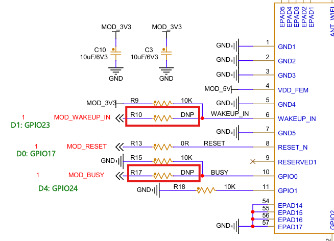
The Seeed XIAO HaLow module has two DNP (Do Not Populate) resistors near the WAKE and BUSY pins on the PCB.
Can I safely short the WAKE (R10) and BUSY (R17) pads on the module and connect them to GPIOs (e.g., WAKE → GPIO23, BUSY → GPIO24) to allow the RPi driver to control them?
Ah, if you’re using SeeedStudio’s fork, then the pinout will change as they have adapted it for their carrier boards.
See this commit, which details the changes.
The RESET line should be connected to GPIO17.
The SPI IRQ line should be connected to GPIO5.
Can I safely short the WAKE (R10) and BUSY (R17) pads on the module and connect them to GPIOs (e.g., WAKE → GPIO23, BUSY → GPIO24) to allow the RPi driver to control them?