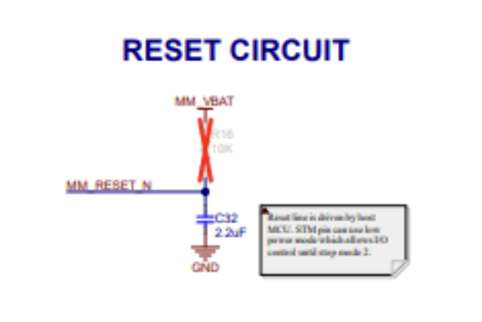
Hi Ottop,
To answer your questions:
What does the note say, and why is the pull-up resistor DNP by default on EKH05?
The 220kΩ + 2.2µF RC network on RESET_N is the recommended default for designs where no host actively controls the pin. It ensures the chip is held in reset long enough to initialize cleanly at power-up.
On the EKH05, the schematic includes a note explaining this: the STM32 host actively drives RESET_N and retains GPIO control through all low-power modes used on that board. Since the host is always in control of the line, the pull-up resistor is marked DNP. For reference, the complete MM8108-EKH05 design package, including the schematic, is available on the customer portal.
Is the pull-up only needed when RESET_N isn’t actively driven by a host GPIO (e.g., standalone/host-independent power-on reset), and safe to omit when the host MCU actively drives RESET_N during boot?
Yes. The pull-up resistor on RESET_N is intended for standalone designs where no host controls the pin, ensuring the pin is held at a defined logic high so the chip is not held in reset.
When a host MCU actively drives RESET_N, the pull-up serves no purpose and can be omitted.
One condition applies: if your MCU ever releases RESET_N to float, for example by entering a deep sleep mode where GPIO state is lost, a pull-up is still required to keep the pin in a defined state.
Any recommendation for a custom board that will always have a host MCU driving RESET_N as a GPIO output?
For a custom board where a host MCU always drives RESET_N as a GPIO output, the pull-up resistor can be omitted. That said, there is no downside to including the pull-up resistor footprint and leaving it unpopulated as it gives you the option to fit it later if needed without a board respin. The MMECH17 and EKH05 schematics are good references alongside the hardware design guide.
Also a quick sanity check while I’m at it — I noticed WAKE and BUSY have no pull resistors on the EKH05 schematic either, left floating when unconnected/unused. Just want to confirm that’s correct and there’s nothing special needed there (e.g. no pull-up on BUSY, no pull-down on WAKE)?
WAKE: The pin is active high and has an internal pull-down, so leaving it unconnected means it will be held low by default. That’s fine if you have power save disabled in firmware as the chip won’t try to sleep. If power save is enabled and WAKE is left floating low, the chip will enter power save and may not behave as expected. So no external resistor is strictly required, but if you want to guarantee always-on behaviour without relying on a firmware setting, a pull-up to VDD is a safe option. Note that leaving WAKE and BUSY unconnected will permanently block power save functionality, so if you anticipate needing power save in the future, connecting these pins is recommended.
BUSY: This is an output from the MM8108, so leaving it unconnected when unused is fine. No pull resistor needed.